
Fire-protection and smoke-ventilation shop drawings translate an approved safety strategy into coordinated, buildable information. They should show how equipment, pipework, ducts, dampers, controls, power supplies, shafts and architectural openings work together in the actual building.
In Abu Dhabi, weak shop drawings can create a chain of problems: authority comments, clashes above ceilings, reduced maintenance access, incorrect detector or sprinkler locations, unbalanced smoke-control systems, failed integrated testing and unreliable as-built records. The solution is not simply more drawing detail; it is better engineering coordination.
Design drawings and shop drawings are not the same
Design documents establish the performance requirements, system concept, code basis and principal arrangement. Shop drawings develop that information around selected equipment, coordinated routes, installation details and construction interfaces.
A contractor’s shop drawing should not silently change the approved design. Where selected equipment, layout constraints or site conditions require a technical change, the responsible designers and relevant approval parties should review it through a controlled process.
What fire-protection shop drawings should coordinate
Water-based fire protection
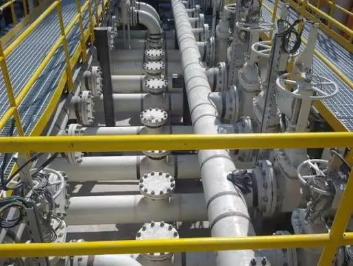
Plans and schematics may need to show fire pumps, tanks, valves, risers, sprinklers, hose reels, hydrants, test and drain arrangements, fire-department connections, zoning, hydraulic design references and access for inspection and maintenance. Pipe routing must be coordinated with structure, ceilings, lights, ducts, cable trays and other services.
Fire detection and alarm
Drawings should coordinate detection, manual call points, notification devices, control panels, loops, interfaces, zoning and device access. The cause-and-effect matrix should match the drawings and the intended emergency sequence.
Special suppression
Clean-agent, water-mist, foam, wet-chemical or other systems require hazard-specific design, enclosure or discharge assumptions, equipment data, interfaces, warning arrangements and safety controls. The selected system must suit the protected risk and current acceptance requirements.
Passive protection interfaces
Fire-stopping, rated shafts, dampers, access panels, doors and penetration seals are often split across packages. Shop-drawing coordination should ensure that active-system routes do not compromise compartmentation.
What smoke-ventilation drawings need to prove
Smoke control is a performance system, not only a duct layout. Depending on the building, the strategy may involve smoke extract, natural ventilation, make-up air, stair or lobby pressurisation, car-park ventilation, atrium control, zoned dampers and firefighter controls.
Coordinated drawings should make the following clear:
- system boundaries, zones and design fire or operating scenarios;
- fan duties, temperature ratings and redundancy where required;
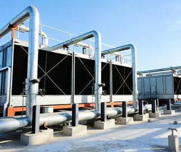
- duct routes, construction, leakage class and fire-resistance requirements;
- intake, make-up-air and discharge locations;
- smoke and fire damper locations, access and fail-safe positions;
- stair, lobby, atrium, basement and car-park interfaces;
- normal HVAC shutdown or changeover sequence;
- emergency power, cabling, controls and firefighter override;
- alarm inputs, cause-and-effect and status monitoring; and
- commissioning measurements and acceptance criteria.
Computational fluid dynamics (CFD) can support complex performance analysis, but it should answer a defined engineering question with agreed inputs and acceptance criteria. A visually impressive simulation cannot compensate for uncertain geometry, fire assumptions, leakage, boundary conditions or uncoordinated controls.
The multidisciplinary coordination sequence
- Confirm the approved basis: code, fire strategy, approved drawings and authority comments.
- Freeze equipment data: duties, dimensions, access, electrical loads, weights and control requirements.
- Coordinate architecture and structure: shafts, louvers, doors, ceilings, openings, plant rooms and fire-rated construction.
- Coordinate MEP routes: resolve sprinkler, duct, cable-tray, lighting and access conflicts at usable clearances.
- Align control documentation: drawings, sequences, I/O points and cause-and-effect must describe the same operation.
- Plan testing early: define points, modes, measurements, witnesses and records before ceilings close.
- Update the final record: approved deviations and test settings must flow into as-built drawings and O&M information.
Current Abu Dhabi competency context
The ADCDA regulations page provides access to Abu Dhabi fire-safety guidance. Requirements should be checked against the current official documents and project approvals rather than copied from an old drawing set.
In addition, the 2026 ADCDA accreditation initiative states that the relevant certification and DMT classification become mandatory from 1 September 2026 for engineering consultancies submitting fire-protection system designs. Project teams should verify who is permitted to design, review and submit the relevant work.
Common drawing failures to prevent
- sprinklers placed before the reflected ceiling, lighting and obstruction layout is stable;
- smoke-extract duties copied from a schedule that no longer matches the design;
- dampers shown without access or control status;
- fire-alarm drawings and cause-and-effect matrix carrying different zone names;
- fire-rated ducts or shafts penetrated without coordinated protection details;
- no safe test or drain route for water-based systems;
- emergency power and control wiring omitted from coordination;
- approved design changes not reflected in hydraulic, ventilation or electrical calculations; and
- as-built drawings created from the shop-drawing issue without site verification.
How Infinity MEA supports buildable fire-safety design
Infinity MEA combines fire-protection engineering, mechanical design, electrical coordination and BIM modelling to develop coordinated design and shop-drawing information. The team can also support submittal registers, authority comments, testing plans and final as-built documentation.
Every project should be checked against current approvals and discipline-specific authorisation requirements. Contact Infinity MEA to review the drawing status, design interfaces and submission needs for your Abu Dhabi project.
Frequently asked questions
Who is responsible for shop-drawing design changes?
Responsibility depends on the contract and appointment, but a shop drawing should not bypass the responsible designer or required authority review. Design changes need documented technical approval.
Do smoke-control systems always require CFD?
No. CFD is used where the strategy, geometry or approval basis calls for performance analysis. Other projects may use prescriptive or calculation-based methods. Confirm the required method early.
When should integrated fire-system testing be planned?
During design. Waiting until handover can reveal missing interfaces, unavailable test modes, access problems or incompatible control logic after finishes are complete.
Can BIM coordination replace engineering calculations?
No. BIM helps coordinate geometry and information, but hydraulic, airflow, pressure, electrical and life-safety performance still require appropriate engineering analysis.
Speak with Infinity MEA about the fire, safety, risk and approval priorities affecting your Abu Dhabi project.
Contact our team Abu Dhabi Fire & Safety Engineering
 Abu Dhabi Fire & Safety Engineering